Plans and sections on paper
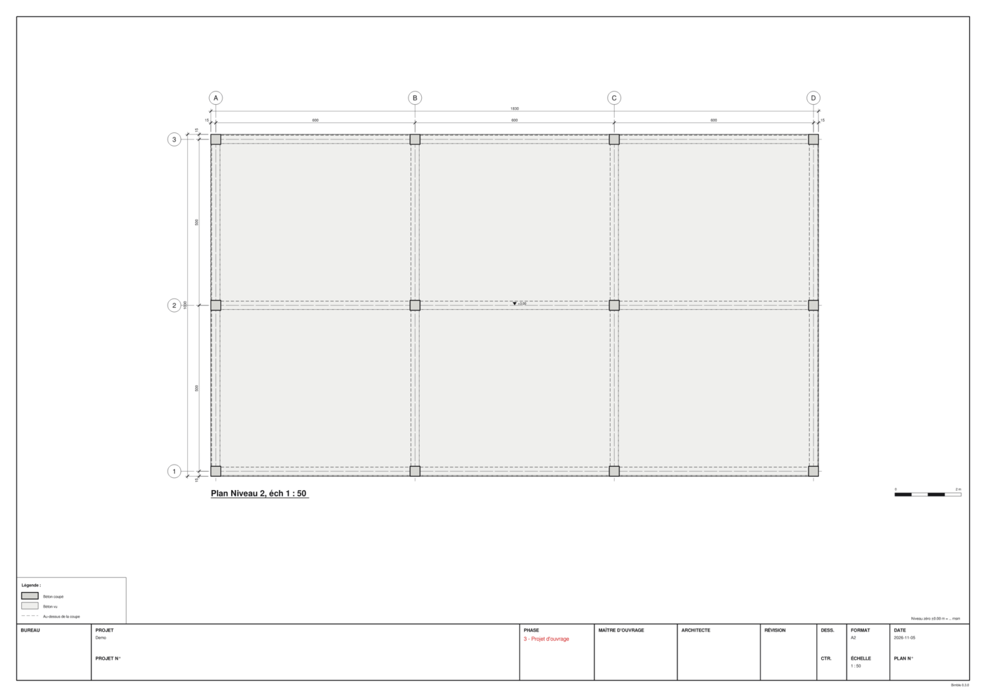
Bimble draws a storey plan, or any plan, ceiling plan or section view, at scale (1:1 to 1:5000), on A4 to A0, as PDF, SVG or PNG. The plan is an exact horizontal section of the model, not a screenshot: a 300 mm column is 3 mm on paper at 1:100.
What a plan shows
The plan cuts the model at a height above the storey level, 1.2 m by default, and looks down:
- Cut: what the plane cuts (walls, columns), filled and hatched by material, with a thick outline.
- Seen: what lies below the cut, down to the storey level (the slab, beams, footings), filled lighter, with thin edges. Higher elements hide lower ones.
- Above: edges of the storey's elements above the cut, up to the next storey, dashed. On a formwork plan, these are the beams under the slab above.
Around the drawing:
- grid axes with bubbles. They come from the model's IFC grid, or, when it has none, are drawn through the cut columns (A, B, C… one way, 1, 2, 3… the other);
- dimension chains on the top and left: first from the outer face through the axes, then the overall size. Dimensions are in cm by default;
- slab levels on the slabs seen below the cut, and a cross in their rectangular openings;
- a legend, the title ("Plan Level 1, 1:100"), a level note, a graphic scale bar and the title block.
Reinforcement, spaces, openings, annotations and terrain are left out.
All of this can be changed with a plan template.
In the viewer
To see a view as it prints, open it and choose On paper in its tab (P, see Model and On paper). To save it, Sheets → Export view…:
| Setting | What it does |
|---|---|
| Draw | Storey plan, or one of the model's plans, ceiling plans and sections. It starts on the view you are looking at |
| Storey | The storey to draw (storey plan only) |
| Scale 1: | A view's own scale; a storey plan's: type a number or pick 50, 100, 200, 500 |
| Paper | A4…A0, or Smallest that fits (landscape or portrait) |
| Cut height | Height of the cut plane above the storey level, mm (storey plan only; a view uses its view range) |
| Seen fills, Axes, Dimensions, Legend, Levels | Switch those parts on or off |
| Template… | Load a plan template (JSON); Default goes back to the built-in one |
Export PDF… and Export SVG… save the sheet. In a browser they download it.
If the plan doesn't fit the paper at that scale, Bimble says so and suggests the scale that fits:
What a plan shows
Besides what is cut and seen, a plan can show, each switched in Annotate → On plans (and in the On paper window), all on by default:
| Switch | Shows |
|---|---|
| Section labels | The section of each cut column, beam, member or pile beside it: "30/30" (cm), "Ø30" for a round one, "GL24h 24x46" for timber with a material name. Beams above the cut of a plan get theirs along them |
| Openings | In rectangular slab openings: their size ("100x200", cm), and their distance to the nearest grid axes, as dimensions |
| Section marks | Where each section view cuts the plan: a dash-dot line across the drawing, thick ends, arrows looking the way the section looks, its tag at both ends. The tag is the last short word of the section's name ("Coupe A" → A), else A, B, C… |
| Levels | Top-of-slab levels on the slabs seen below the cut |
The template keys are element_labels, opening_dimensions, section_markers and slab_levels.
Pens, line types, text sizes and hatches come from the Standards.
From the command line
bimble info model.ifc                                  # lists the storeys and their levels
bimble plan model.ifc plan.pdf --storey "Level 1"      # 1:100, smallest paper that fits
bimble plan model.ifc plan.svg --storey "Level 1" --scale 50 --paper A1
bimble plan model.ifc plan.png --storey "Level 1" --dpi 200
bimble plan model.ifc plan.pdf --storey "Level 1" --cut 900   # cut 0.9 m above the level
A view, by its name (bimble views lists them; letter case doesn't matter):
bimble views model.ifc                                          # plans, ceiling plans, sections
bimble plan model.ifc ceiling.pdf --view "Ceiling Level 1"
bimble plan model.bimble section.pdf --view "Section 1 (looking north)" --scale 50
For an IFC file, its views come from model.ifc.bimble-views.json next to it, if there is one.
The output's extension chooses the format. All the options are in the command-line reference.
Ceiling plans and sections
They are drawn the same way as plans, turned to look straight at the view:
- a ceiling plan looks up from its cut plane to its view depth, with north up and east to the right, like the screen: the slab soffit and beams are seen, the columns are cut;
- a section is cut through its point, looking north, east, south or west, and shows what lies beyond the cut up to its depth (all of it when the depth is 0).
What the view hides (its Visibility) is left out on paper too. Grid axes and slab levels are drawn on plans only; their title is the view's name ("Ceiling Level 1, 1:100").
Your office's plans: templates
The title block, the words on the sheet and what is shown come from a plan template, a JSON file. A template lists only what differs from the built-in English one.
bimble plan-template > my-office.json           # the full default, to start from
bimble plan-template my-office.json             # checks a template and prints it in full
bimble plan model.ifc plan.pdf --storey N01 --template my-office.json \
    --field phase="Projet d'ouvrage" --field drawing_no=S-101
A French template in the layout of a Swiss engineering office's formwork plans is included:
docs/templates/plan-fr.json.
It has Béton coupé and Béton vu in the legend, Plan N01, éch 1 : 100 as the title, and a title
block with project, phase (in red), client, architect, revision, drawn/checked, format/scale and
date/plan number.
Values such as the phase or the client go in the template's fields, or on the command line with
--field key=value. Every key is described in the plan template reference.
Colours, hatches and pen widths come from the graphic style, not the template.
Limits
- What is seen below the cut is painted from the lowest element to the highest. Each element hides its own hidden parts, sloped and stepped tops included, but an element that overhangs another at a lower height can show wrong lines.
- Sections have no grid axes or level marks yet (#24).
- Opening dimensions go to the nearest grid axes only, not to the nearest face.
- Section marks are drawn on plans, not on other sections.