Views and reference plans
A model has several views: 3D views, plans looking down, ceiling plans looking up, and sections. Each view keeps its own camera, what it hides and its reference plans. You select, edit and measure elements in a plan or a section exactly as in 3D.
The model navigator
The top of the left panel lists everything in the model:
| Section | Holds |
|---|---|
| Views | 3D views, Plans, Ceiling plans (looking up), Sections. Click one to open it |
| Schedules | Tables of elements and quantities: click one to open it (schedules) |
| Layouts | The sheets: click one to open it; New sheet |
| Objects | The elements by IFC class. Click one to select it and frame it |
| Links | The linked models, and every reference plan with its view |
| Measurements | The dimensions you took (see Measuring) |
| Warnings | Problems found while reading the file |
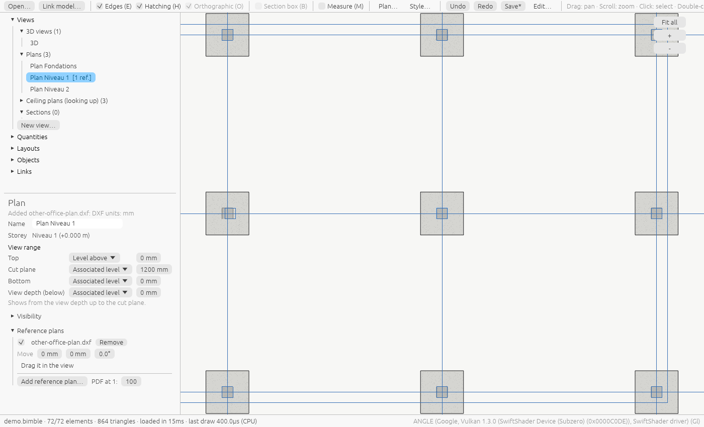
A view with reference plans shows how many, such as Plan Niveau 1 [1 ref.].
The views you start with
Every model has, without anything to set up:
- 3D;
- Plan storey for each storey, looking down;
- Ceiling storey for each storey, looking up.
New views
New view… under the list makes:
- a plan or a ceiling plan of any storey;
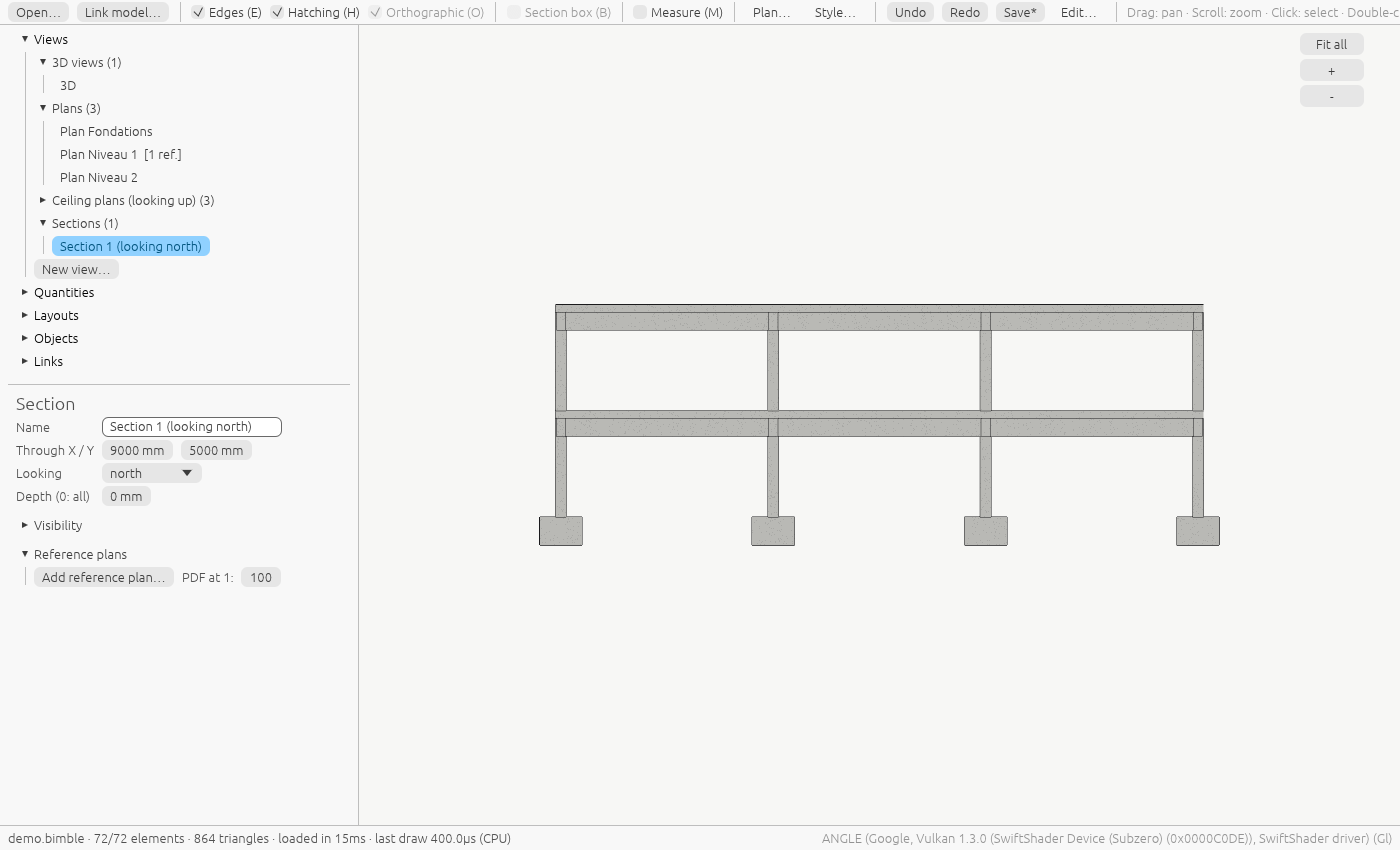
- a section looking north, east, south or west, through the middle of the model;
- another 3D view.
Right-click a view for Duplicate, or Delete. A view you started with can't be deleted, but once you have changed it, Reset to default brings it back as it was.
Plans and sections
In a plan or a section:
- the camera looks square to the view; drag to pan, scroll to zoom, double-click or F to fit;
- the view cube, Home, the section box and perspective are off: the view is cut by its range;
- clicking selects, the properties panel edits, M measures, as in 3D;
- placing elements (Model tab) in a plan puts them on that plan's storey.
Ceiling plans look up at the underside of the floor above, like a reflected ceiling plan: north stays at the top and east on the right.
Project north and true north
As in Revit, plans and sections are drawn in project north: along the building, whatever its
turn in the site. Bimble reads the turn from the IFC (the building's placement, or an IFC4 map
conversion). A section looking north looks along the building's north, on screen and on
paper. To draw a view with true north at the top, set its Orientation to True north in
the view's properties. A model whose building isn't turned is drawn the same either way.
bimble info prints the survey system and the turn.
Coordinates
The status bar gives the coordinates of the point under the pointer (on an element, or on a plan's cut), and of the point you snap to while measuring:
- in the model's survey system: for Swiss models LV95, the Swiss way,
E 2'600'123.45 N 1'200'456.78 · 432.10 m (LV95); - or, in Settings → Coordinates: WGS84 latitude and longitude (GPS), ETRS89 / UTM in the point's zone (Europe), or another system: Swiss LV03, or a US State Plane zone (NAD83, in metres, feet or US survey feet; type a state or "ftUS" to find it). They are worked out from the model's survey system (as PROJ does).
A model whose survey system isn't known shows metres in its own coordinates.
View range
A plan shows what lies between two heights, set in its properties under View range:
| Plane | Looking down | Looking up |
|---|---|---|
| Top | Upper limit of the view's range | Upper limit of the view's range |
| Cut plane | Where the model is cut; you see down from here | Where the model is cut; you see up from here |
| Bottom | Lower limit | Lower limit |
| View depth | How far below the cut you see | How far above the cut you see |
Each plane is a level and an offset in mm:
- Associated level: the plan's storey;
- Level above or Level below: the next storey up or down;
- Unlimited: no limit (the offset is then ignored).
A plan looking down shows from the view depth up to the cut plane; a ceiling plan, from the cut plane up to the view depth.
The planes must be in order, from the bottom up:
- looking down: view depth ≤ bottom ≤ cut plane ≤ top;
- looking up: bottom ≤ cut plane ≤ top ≤ view depth.
A range out of order is refused with a message, and the view keeps its previous range.
The usual cut is 1.2 m above the storey looking down and 2.3 m looking up. On a storey lower than that, such as a foundation level, the cut starts at half the storey's height.
Sections
A section's properties set:
- Through X / Y: the point the section passes through, in mm;
- Looking: north, east, south or west;
- Depth: how far beyond the cut you see, in mm; 0 shows everything.
Visibility
Each view has its own Visibility list: material families, IFC classes and storeys. Untick one to hide it in this view only. The plan of a storey can hide the footings while the 3D view shows everything. Sheets and PDFs of the view leave out the same.
Each family opens (▸) into the materials found in the model, each with its own checkbox, and a drop-down to draw that material as another family (its colour and hatches): useful when Other holds most of the model. That choice is saved in the graphic standards, so it applies to every model; the Standards panel lists the moved materials, each with × to undo it. A click on a family's colour square opens its colour in the Standards panel.
Reference plans
A reference plan is another office's drawing, such as the architect's floor plan, laid over a plan or a section to check that the geometry matches and to measure on it.
- It is shown only in its view.
- It is dead geometry: its lines can't be selected or changed, only moved.
- It is drawn in the reference colour (blue by default).
Add one
- Open the plan or section.
- Collaborate → Link DXF or Link PDF; or, in the view's properties under Reference plans, Add reference plan…; or drop the file on the window.
- Pick the file:
- DXF: read with its units (
$INSUNITS; millimetres when the file doesn't say). Lines, arcs, circles, ellipses, polylines (with arcs), splines, solids, and blocks are read, from model space; text and hatches are not (the message counts what was left out). - PDF: the vector lines of the first page. Set its scale in PDF at 1: before adding it (1:100 by default). A scanned PDF has no lines to read.
- DWG: not read directly. Convert it to DXF first, with the free
ODA File Converter or LibreDWG's
dwg2dxf.
- DXF: read with its units (
A DXF drawn in the project's coordinates lands where it belongs. When the plan's coordinates are far from the model (a PDF, a drawing at the origin), it is centred on the model and the message says so: then move it into place.
Move it into place
- Type the Move offsets (X and Y in mm, along the view) and the rotation in degrees, or
- turn on Drag it in the view and drag: the plan follows the mouse. Turn it off to pan again.
Measure on it
With Measure (M) on, points snap to the reference plan's corners and lines as well as to the model. Measure from a column of the model to the same column on the architect's plan to see how far apart they are.
Hide or remove it
The tick box next to its name shows or hides it; Remove takes it out of the view. A new version of the file: Collaborate → Manage links → Reload (or Reload from…), and the lines change where the plan was placed.
Model and On paper
A plan, ceiling plan or section has two pictures, switched at the right of its tab (Model | On paper) or with P:
- Model: the model itself, instant even on large models, where elements are placed, moved and measured.
- On paper: exactly the drawing its PDF and sheets are made of: pens and texts at the view's scale, hatches, dashed lines above the cut, grid axes, dimension chains, the view's own dimensions and texts. Scroll zooms at the pointer, a drag pans, F fits. The status bar says the scale, the scale it is seen at on screen, and how long it took to draw.
On paper, a click selects the element drawn there: the one cut there, or seen below. Its properties show on the left and its outline on the paper; Ctrl (Cmd on a Mac) adds to the selection. Pointing at an element names it in the status bar. Double-click goes to the model at that place. Placing and measuring switch to Model. Both pictures show the same view: its range, visibility, scale and annotations.
Crop
A plan or section can draw only part of itself: in its properties, tick Crop (it starts from the whole model), then To the screen to keep what the screen shows now (zoom on the part you want, then click), or type the extent in metres (x along, y across; for a section, along the cut and height). Model and On paper are cropped alike; the drawing's axes, dimension chains and page follow the crop. Untick Crop to see it all again.
When a view changes, its drawing On paper (and a sheet's) is made again in the background: the last one stays, greyed, with Drawing… n s, and the window can be used meanwhile. A section through a very large model can take several seconds.
Scale
A view's Scale 1: (its properties) sets its pens, texts and dimensions on paper and on screen, and its size on every sheet it is placed on. To show a plan at two scales, duplicate the view. A file from before 0.15 whose sheets placed a view at another scale opens with the view taking that scale, as a change to save.
To print or export a view, Sheets → Export view… (Plans and sections on paper); Sheets put several views on one page.
Where views are saved
- In a
.bimblemodel, views are part of the model: saved with it, undone with Ctrl+Z, and kept in its history. - An IFC file is never changed. Its views go in a file next to it, named after it:
model.ifc.bimble-views.json. Save, or Ctrl+S, writes it; it is read the next time you open the IFC. In a browser, it is downloaded instead; open or drop it after the IFC to get the views back.
Reference plans are stored inside the view (as lines in mm), so the model or the side file carries them: the original DXF or PDF is no longer needed.